


The UF Capacitors CBB237 is a metallized polypropylene film AC filter capacitor designed for medium- and high-power power-electronic systems. The supplied 250µF model is rated at 600VAC (Urms), with 850VAC nominal voltage, 1.4mΩ ESR at 1kHz and 25°C, and up to 64A maximum current at 55°C ambient. Its cylindrical aluminum housing, self-healing metallized PP film and integrated overpressure disconnect make it suitable for AC filtering in solar and wind inverters, industrial UPS systems, and high-power drives.
• 250µF ±5% capacitance with 600VAC rated AC voltage.
• Low ESR: 1.4mΩ at 1kHz, 25°C.
• Maximum current: 64A at 55°C ambient.
• Peak impulse current: 3.3kA / 9.9kA according to the supplied specification.
• 100,000-hour life expectation at 0.8 Urms and 70°C hotspot under the stated life-test conditions.
• Integrated overpressure disconnect and self-healing metallized polypropylene construction.
• Designed for AC filtering and harmonic-current handling in renewable-energy and industrial power-conversion equipment.
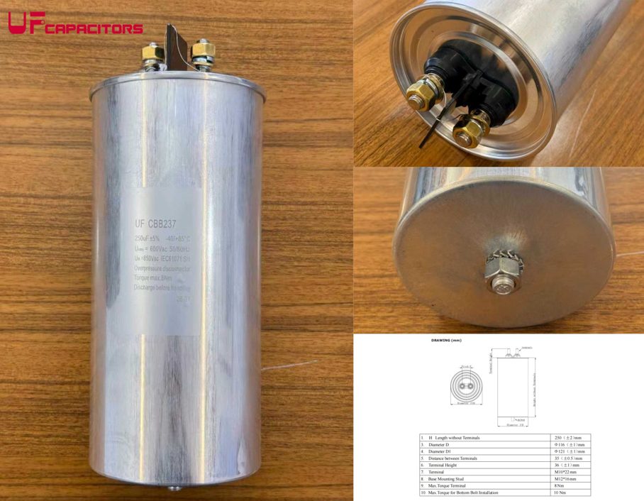
Figure 1. UF CBB237 cylindrical AC filter capacitor and terminal / mounting details.
CBB237 is a power film capacitor built around self-healing metallized polypropylene (PP) film. In an AC-filter stage, the capacitor carries harmonic and ripple current while helping attenuate switching-frequency components and smooth the AC waveform. Compared with general-purpose film capacitors, an industrial AC-filter capacitor must be selected not only by capacitance and voltage, but also by ESR, RMS current, thermal conditions, impulse current, lifetime and safety-disconnect behavior.
|
Parameter |
Supplied CBB237 Specification |
|
Series / Model |
CBB237 |
|
Rated Capacitance |
250µF |
|
Capacitance Tolerance |
±5% |
|
Rated AC Voltage (Urms) |
600VAC |
|
Nominal Voltage (UN) |
850VAC |
|
Rated Frequency |
50 / 60Hz |
|
ESR |
1.4mΩ @ 1kHz, 25°C |
|
Maximum Current (Imax) |
64A @ ambient 55°C |
|
Peak Impulse Current |
3.3kA / 9.9kA |
|
Self-Inductance |
≤190nH |
|
Dielectric |
Polypropylene film + Al/Zn metallized film |
|
Case |
Cylindrical aluminum case, soft PU resin potting |
|
Dimensions |
Ø116mm × 250mm |
|
Main Terminals |
M10 screw terminals, max. 8N·m |
|
Bottom Stud |
M12, max. 10N·m |
In inverter and UPS output filters, capacitor losses convert ripple current into heat. Lower ESR helps reduce internal power dissipation for a given RMS current, while current rating and thermal design determine whether the capacitor can operate within its hotspot limit. For the supplied CBB237 model, the published ESR is 1.4mΩ at 1kHz and 25°C, and the maximum current is 64A at 55°C ambient.
These values should be evaluated together rather than independently. A designer should confirm expected harmonic spectrum, RMS current, ambient temperature, airflow, mounting arrangement and hotspot temperature before approving the capacitor.
|
Item |
Supplied Test Condition / Performance |
|
Life Expectancy |
100,000h at 0.8 Urms, hotspot 70°C, |ΔC/C| ≤5% |
|
Failure Rate |
≤200 FIT |
|
Operating Temperature Range |
-40°C to +85°C |
|
Recommended Hotspot for Maximum Life |
≤70°C |
|
Safety Protection |
Integrated overpressure disconnect device |
|
Terminal-to-Terminal Test Voltage |
2.15 × Urms, 50/60Hz, 10s |
|
Terminal-to-Case Test Voltage |
4000VAC, 50/60Hz, 10s |
|
High-Temperature Durability |
1.25 × Urms at 70°C for 500h, ΔC/C ≤ ±3% |
|
Damp Heat |
40°C, 93% RH, 56 days, ΔC/C ≤2% |
|
Environmental Compliance |
RoHS stated in supplied specification |
The CBB237 is aimed at power-electronic systems where substantial AC ripple or harmonic current must be filtered over long operating periods.
AC output filtering and power conditioning in wind-turbine converters.
AC-side harmonic filtering in central or high-power photovoltaic inverters.
Output filter stages in three-phase uninterruptible power supplies.
Filtering switching harmonics and supporting high-power AC conversion stages.
• Capacitance: confirm the required filter capacitance and tolerance under the actual circuit topology.
• AC voltage: verify continuous RMS voltage, repetitive peak voltage and transient conditions.
• RMS / harmonic current: calculate the actual capacitor current spectrum and compare it with the manufacturer's current limit.
• ESR and heating: estimate capacitor loss and confirm hotspot temperature under worst-case ambient conditions.
• Impulse / surge current: check repetitive and non-repetitive current stress against published limits.
• Mechanical installation: confirm can diameter, height, terminal torque, bottom stud and required pressure-disconnect clearance.
• Lifetime target: compare the intended mission profile with the supplier's lifetime curve / stated test conditions rather than quoting 100,000 hours as an unconditional life.
The supplied CBB237 installation guidance is especially important because the safety deck must be able to move when the overpressure disconnector operates.
• Mount the capacitor vertically with terminals facing upward.
• Keep at least 25mm free space above the terminal / safety-deck area.
• Maintain at least 10mm spacing between adjacent capacitors for thermal dissipation.
• Use flexible stranded wiring rather than rigid connections that can mechanically restrain the safety deck.
• Discharge through a suitable resistor before maintenance; do not use direct short-circuit discharge.
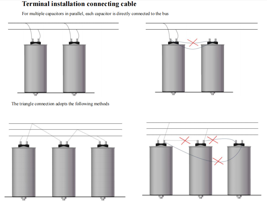
Figure 2. Terminal connection and installation guidance from the supplied CBB237 document.
|
Selection Factor |
CBB237 Power AC-Filter Type |
Generic Film Capacitor |
|
Primary design focus |
High-power AC filtering |
Varies by series |
|
Capacitance |
250µF in this article |
Often much lower or broad range |
|
Current capability |
64A stated for this model |
Must be checked by exact part |
|
ESR |
1.4mΩ stated at 1kHz / 25°C |
May not be optimized for high AC current |
|
Impulse capability |
kA-level values stated |
Highly part-dependent |
|
Safety disconnect |
Integrated overpressure disconnect |
Not universal |
|
Mechanical format |
Large aluminum can, screw terminals |
Many package styles |
|
Typical use |
Inverters, UPS, wind / solar power conversion |
General filtering, snubber, EMI or other functions |
• Direct factory sourcing for industrial film-capacitor projects.
• Engineering support for capacitance, voltage, mounting and application requirements.
• Customization options stated in the supplied article, including mounting and discharge-resistor configurations.
• Product positioning for renewable-energy, UPS and industrial power-conversion applications.
• Sample and technical-document support for project qualification.
It is used in high-power AC filter stages to carry harmonic/ripple current and reduce switching-related AC waveform distortion. Typical applications include wind converters, solar inverters, industrial UPS systems and motor drives.
The supplied CBB237 specification states 1.4mΩ at 1kHz and 25°C.
The supplied specification lists a maximum current of 64A at 55°C ambient. Actual suitability still depends on harmonic spectrum, cooling, mounting and hotspot temperature.
The supplied specification states 100,000 hours under the defined condition of 0.8 Urms and 70°C hotspot with capacitance change limited to |ΔC/C| ≤5%. It should not be interpreted as an unconditional 100,000-hour life at every voltage and temperature.
The supplied specification describes self-healing metallized polypropylene construction and an integrated overpressure disconnect device.
The supplied guidance calls for vertical mounting with terminals upward, at least 25mm clearance above the safety-deck area and at least 10mm spacing between adjacent capacitors.
Yes. The supplied product application information specifically lists renewable-energy converters, including wind-power and solar/PV inverter AC filtering.
Compare RMS voltage, peak/transient voltage, RMS/harmonic current, ESR, impulse-current limits, dimensions, terminal design, safety-clearance requirements and lifetime conditions. Capacitance and voltage alone are not enough.
|
Visual |
Content |
SEO / GEO Value |
|
Hero Product Graphic |
CBB237 can + 250µF / 600VAC / 64A / 1.4mΩ |
Immediate product/entity recognition |
|
AC Filter Circuit Diagram |
Inverter → LC/LCL filter → grid/load; highlight capacitor position |
Explains application rather than only showing product |
|
Thermal / Current Infographic |
ESR + RMS current → internal heating → hotspot → lifetime |
GEO-friendly engineering explanation |
|
Installation Clearance Diagram |
25mm top clearance + 10mm spacing + flexible leads |
Captures practical installation searches |
|
Application Map |
Wind / PV / UPS / motor drive |
Supports long-tail application keywords |
This article was restructured from the supplied UF CBB237 product material into a technical Products News guide. Numerical specifications are kept tied to the supplied CBB237 source; broader application and selection explanations are framed as engineering guidance rather than as additional unverified product specifications.
Primary product source: UF Capacitors CBB237 article / specification supplied for this revision. External web checking found public UF-branded CBB237 marketing material consistent with the headline values 250µF ±5%, 600VAC, 850VAC and -40°C to +85°C. The UL810 file reference should be internally verified before making a certification-ownership claim.