


Due to the different dielectric materials used in ceramic capacitors (MLCCs), certain types exhibit DC bias characteristics. Specifically, their actual capacitance decreases as the applied DC voltage increases, as shown in the graph below. The rate of change depends on the temperature coefficient and nominal capacitance.
High-permittivity MLCCs, such as X5R, X6S, and X7R, exhibit DC bias characteristics and also show significant capacitance variation with temperature. In contrast, C0G (temperature-compensating MLCCs) have minimal temperature drift and no DC bias effect.
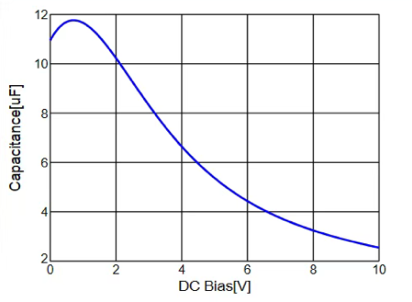
Suppose we need to add an output capacitor to an LDO with a 5V output. The recommended capacitance is 5μF. To ensure sufficient voltage margin, we select a 10V-rated Murata MLCC (ignoring tolerance and temperature effects for now). After checking the datasheet, we find that a 10μF, 0805 capacitor exhibits the DC bias curve shown below. At 5V DC bias, its actual capacitance is exactly 5μF, meeting the requirement.
But what if we cannot access the DC bias curve for the chosen capacitor? The solution is to use a larger package.
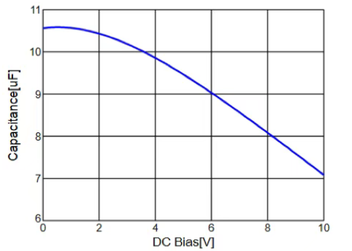
For example, a 10μF, 10V, 1206 MLCC has the DC bias curve shown below. Under a 5V DC bias, its actual capacitance is 9.3μF, significantly higher than the 5μF of the 0805 package.
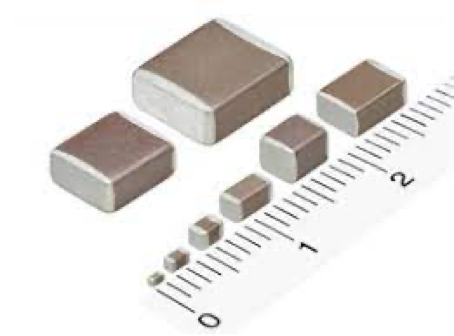
Under the same rated capacitance, smaller packages typically have lower voltage ratings and stronger DC bias effects—meaning their actual capacitance drops more sharply with applied voltage.
General Guidelines for Optimal DC Bias Performance (X7R, 10μF Example):
For MLCCs with 10nF or lower capacitance, DC bias can usually be ignored in practical applications because designers typically leave at least a 2x voltage margin. Thus, package size can be chosen freely. Only larger-capacitance MLCCs require careful package selection to mitigate DC bias effects.
If you are looking for more SMD MLCC or disc ceramic capacitors,
Welcome send us inquiry: carey@ufcapacitors.com