


In power supplies, whether linear or switch-mode power supplies using AC sources and diodes, smoothing capacitors are typically used to smooth the raw rectified output before it is applied to any regulator or similar electronic circuit.
Aluminum electrolytic capacitors are ideal for smoothing because many can provide sufficiently high capacitance and handle the ripple current levels required to smooth the waveform.
Essentially, smoothing circuits fill in the major drops in the raw rectified waveform so that linear regulators or switch-mode power supplies can function properly.
Smoothing capacitors change the waveform from one with voltage varying from zero to peak voltage within the input power waveform period to one with very small voltage changes. In essence, they smooth the waveform, which is why they are named as such.
Since smoothing capacitors are used in linear regulators and switch-mode power supplies, they are crucial components in many such electronic circuits.
Capacitor smoothing is used in most types of power supplies, whether linear regulated, switch-mode, or simply smoothing and non-regulated forms.
The raw DC provided by the rectifier consists of a series of half-sine waves, with the voltage varying between 0 and √2 times the RMS voltage (ignoring any diode and other losses).
This type of waveform is useless for powering circuits, as any analog circuit would have large ripple levels on the output, and any digital circuit would not function because the power is removed every half-cycle.
Capacitor smoothing allows the subsequent stages of linear or switch-mode power supplies to operate correctly.
To smooth the rectifier output, an energy-storing capacitor is used—placed at the output of the rectifier and in parallel with the load.
Smoothing works because when the rectifier voltage rises above the capacitor’s voltage, the capacitor charges, and when the rectifier voltage drops, the capacitor provides the required current from its stored charge.

Figure 1: Full-Wave Rectifier with Smoothing Capacitor
In this way, the capacitor can provide charge when the rectifier is unavailable, so the voltage variation is much smaller than without a capacitor. Capacitor smoothing does not provide total voltage stability; there will always be some voltage variation. In fact, the higher the capacitance, the greater the smoothing, the less current is consumed, and the better the smoothing.
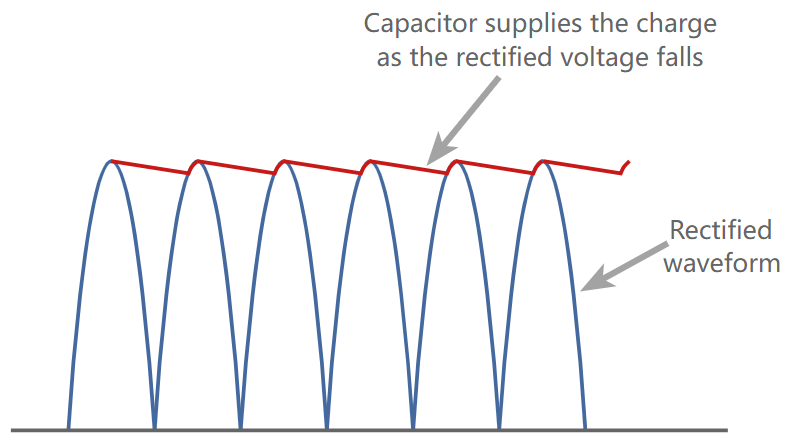
Figure 2: Smoothing Effect of the Energy Storage Capacitor
It should be noted that, aside from internal leakage, the only path for capacitor discharge is through the load to the rectifier/smoothing system. Diodes prevent backflow through components like transformers. Another point to remember is that capacitor smoothing does not provide any form of regulation; the voltage will vary according to load and any input changes. Voltage regulation can be provided by linear regulators or switch-mode power supplies.
Half-Wave and Full-Wave Rectification
Both half-wave and full-wave rectifier systems can be used. In half-wave rectification, one half of the waveform is blocked and not used. This means the waveform consists of a series of half-wave segments with intervals corresponding to the half-waves.

Figure 3: Comparison of Half-Wave and Full-Wave Rectifier Operation
Full-wave rectification utilizes both halves of the waveform, resulting in no large gaps when no voltage is provided.
Using full-wave rectification not only improves efficiency but also allows for better smoothing due to the smaller gaps between waveform peaks.

Figure 4: Full-Wave Rectifier Provides Better Smoothing
Whenever possible, full-wave rectification is always preferable because it achieves better smoothing.
It can also be observed that the fundamental waveform frequency of a half-wave rectifier output is the same as the input frequency. For a full-wave rectifier, it is doubled because the latter half of the waveform is utilized, and the peaks occur at twice the input frequency.
Smoothing Capacitor Value
The choice of capacitor value needs to meet several requirements. In the first case, the value must be selected so that its time constant is much longer than the time interval between consecutive peaks of the rectified waveform

Rload = Total load resistance of the power supply
C = Capacitance value (farads)
f = Ripple frequency — this will be twice the line frequency when using a full-wave rectifier.
Since there will always be some ripple at the output of a rectifier circuit using a smoothing capacitor, it is necessary to estimate an approximate value. Specifying a capacitor that is too high will increase cost, size, and weight, while specifying one that is too low will result in poor performance.

Figure 5: Peak-to-Peak Ripple Output of the Smoothing Capacitor on the Power Supply (Full-Wave)
The figure above shows the ripple of a full-wave rectifier with capacitive smoothing. With a half-wave rectifier, half of the peaks are missing, and the ripple is approximately twice the voltage. For cases where the ripple is relatively small compared to the power supply voltage (which is almost always the case), the ripple can be calculated based on an understanding of the circuit conditions.
Full-Wave Rectifier

Half-Wave Rectifier

These equations provide sufficient accuracy. Although the discharge of a capacitor in a purely resistive load is exponential, for low ripple values, the error introduced by linear approximation is very small.
It is also worth noting that the input to a regulator is not a pure resistive load but rather a constant current load. Finally, the tolerance of electrolytic capacitors used in rectifier smoothing circuits can be quite large, up to ±20%, which will obscure any inaccuracies introduced by assumptions in the equations.
Ripple Current
The two main specifications of a capacitor are its capacitance and working voltage. However, for applications where significant currents may flow, such as smoothing capacitors in rectifiers, a third parameter is crucial — its maximum ripple current.
Ripple current is not merely equal to the power supply current. There are two cases:
Capacitor Discharge Current: During the discharge cycle, when the output of the rectifier circuit drops to zero, the maximum current provided by the capacitor occurs. At this moment, all the current from the circuit is supplied by the capacitor, which equals the total current of the circuit.

Figure 6: Peak Current Provided by the Capacitor During the Discharge Phase
Capacitor Charging Current: During the charging cycle of a smoothing capacitor, the capacitor needs to replenish all the lost charge, but this can only occur when the rectifier voltage exceeds the voltage of the smoothing capacitor. This only happens for a short period within the cycle. Therefore, the current during this period is much higher. The larger the capacitor, the better the ripple reduction, and the shorter the charging cycle.
Shorter charging times result in very high peak current levels because the smoothing capacitor needs to absorb enough charge in a very short time for the discharge cycle.

Figure 7: Time for Power Supply Capacitor Charging
Pi Section Smoothing Network
In some applications, linear regulators are not used, and improved smoothing may be required. This can be achieved by using two capacitors and an inductor or resistor in series.
Smoothing power methods are used in some high-voltage systems and other specialized areas, but they are not as common as linear regulators and switch-mode power supplies, which offer better regulation and smoothing.
This method can also be seen in many old radio devices where using a linear regulator was not feasible.

Figure 8: Pi-Section Smoothing Filter
There are two options for a π-section smoothing system. There are two capacitors between the line and ground, and the series component can be either an inductor or a resistor. Inductors are more expensive but offer better performance, while resistors are a cheaper choice, though they do consume more power.。
Smoothing capacitors are fundamental components in both linear and switch-mode power supplies, and they are used extensively.
When selecting energy storage capacitors for smoothing applications in power supplies, the capacitance value is crucial not only for reducing the required ripple voltage but also for ensuring that the capacitor’s ripple current rating is not exceeded. Excessive current can cause the capacitor to overheat, shortening its expected lifespan, or in extreme cases, lead to failure, sometimes even catastrophic failure.

UF Capacitors supply SMD low impedance aluminum electrolytic capacitor from 6.3V to 100V, high quality can cross to Rubycon TZV,TPV series, Nichicon UUD,UUA UWD series, Panasonic EEE-FK series.
If you are trying to find more alternatives for your design house and EMS,
Pls visit our website at: www.ufcapacitors.com
Or you can send RFQ directly to our sales : carey@ufcapacitors.com
Thanks you for your reading.